Índice
- Machine characterization
Model 2D
Model 3D
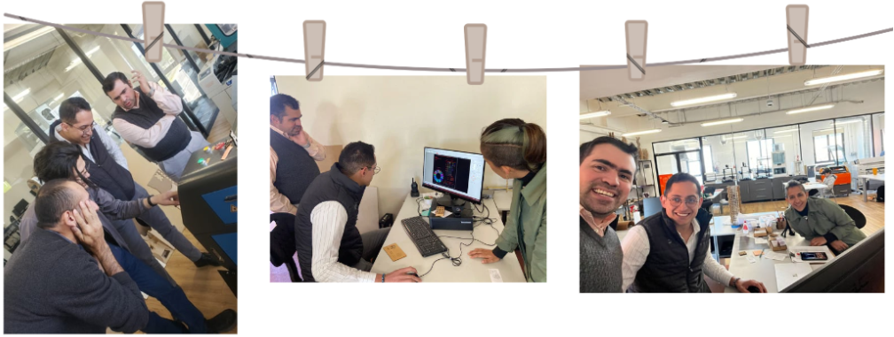
Teamwork
Getting Started
For this team project, the LaserCA software was used, Link de software (Laser CA). Link machine (Boye laser 9060)
Link: FabLab Qro Week 3
Link teamwork:
Machine characterization
For this week, our advisors shared a template for the characterization of the laser cutting machine. This template allowed us to identify the parameters to use for 3 different materials: MDF, acrylic, and corrugated cardboard. This evidence presents the results of MDF.
Step 1: Import template
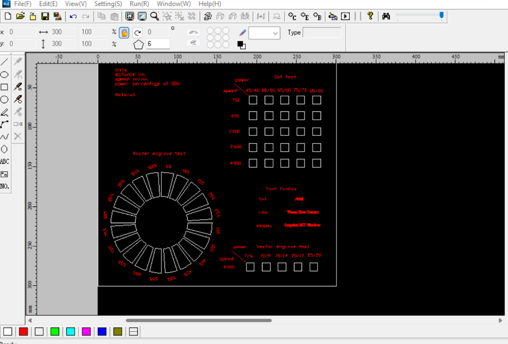
To import (Ctrl+I) the template to the LaserCAM software. (Fig. 1)
Fig. 1. Template in LaserCA
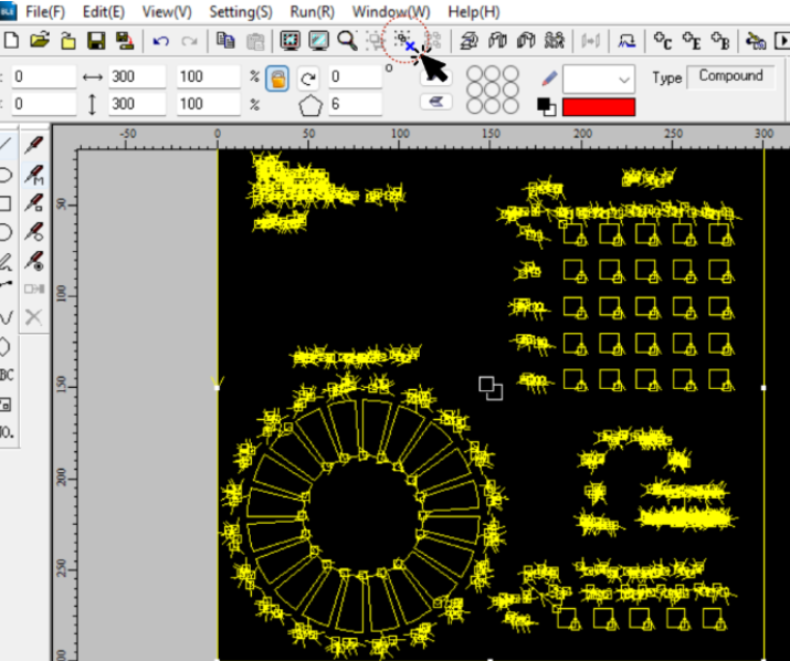
When importing the piece into the software, it remains grouped as a single piece. To manipulate each element independently, it is necessary to ungroup the .dxf file. To do this, select the entire element and then select the 'Ungroup' tool, as shown below (Fig. 2).
Fig. 2. Ungroup.
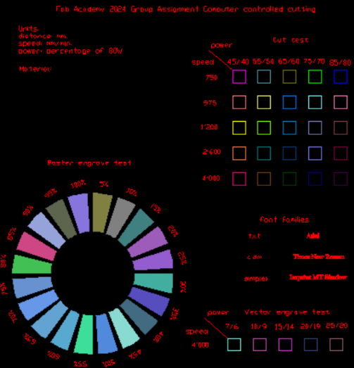
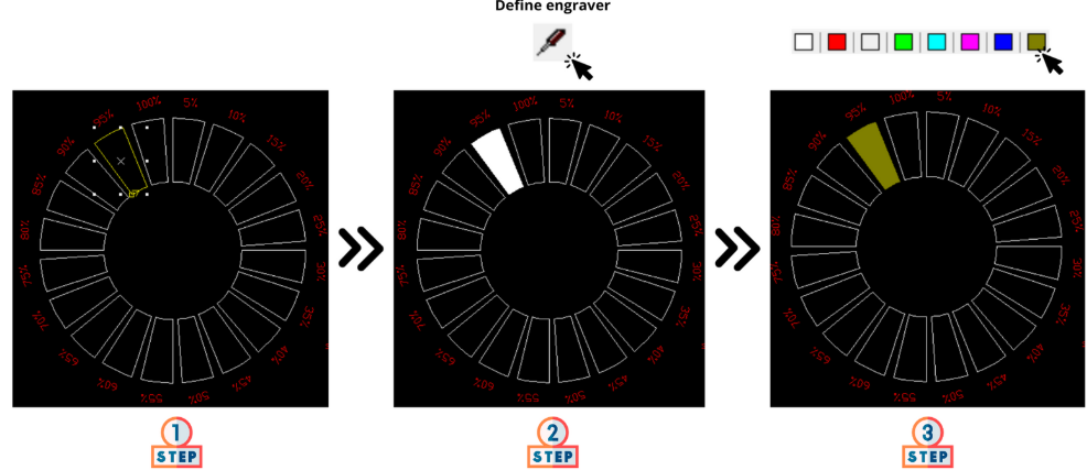
After ungrouping the lines of the .dxf file, it allows us to select each element independently. Then, we select each cutting element and assign it a unique and different color from all the others. This way, we will identify each of them in the software to confirm the cutting or engraving configuration defined by the template (Fig. 3).
Fig. 3. Color assignment.
It's important to mention that to assign a color to the engraving, it is necessary to first mark those lines as engraving using the 'Define Engraver' tool located on the toolbar on the left side. Once the 'Define Engraver' is set, you can now assign a color to the engraving (Fig. 4).
Fig. 4. Define engraver.
Step 2: Settings
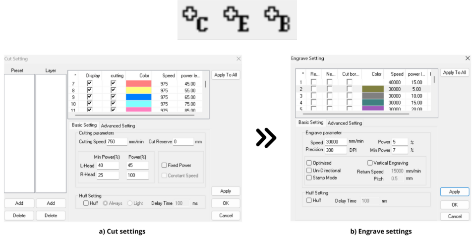
Subsequently, the cutting, engrave, and vector cutting parameters indicated in the template were set using the toolbar in the settings section (C=cut & E=engrave), as shown in Fig. 5. (Fig. 3).
Fig. 5. Toolbal & Settings configuration.
Step 3: Before cut
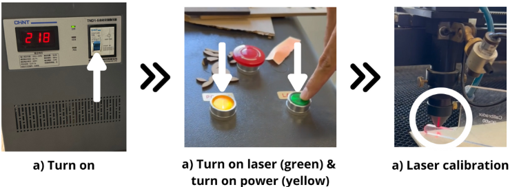
Before starting the cutting process, it is necessary to prepare the machine. As the first step, the machine is turned on using a switch ((Fig. 6 a))). Next, the smoke extractor is connected, and the machine's power button is pressed ((Fig. 6 b))). It's important to note that to calibrate the laser height, it must be turned off. Then, the correct laser height is set using a calibrator (Fig. 6 c)).
Fig. 6. Before cut.
Step 4: Starting cutting
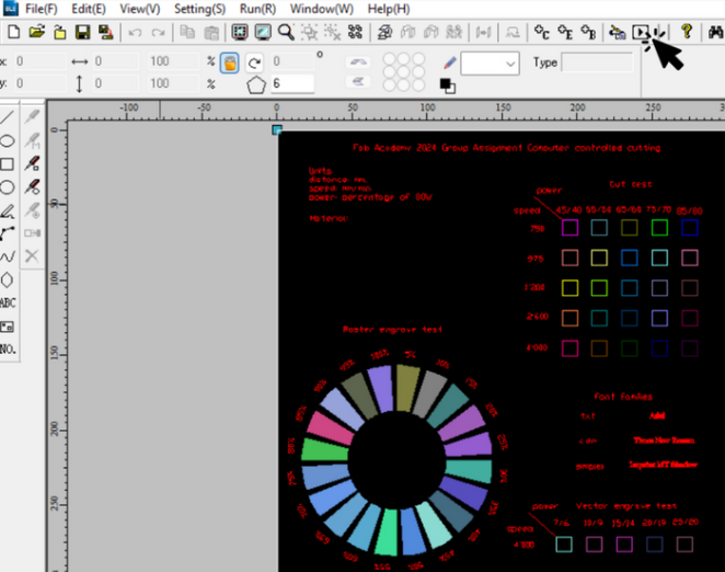
After finishing the cutting, engraving, and machine preparation settings, we can now send the file to the machine to start the process using the 'download' tool, as shown in Fig. 7.
Fig. 7. Download file to machine.
Step 5: Cut
Before starting to cut, it is necessary to load the material onto the machine and set the spindle home position. (Fig. 8).
Fig. 8. Set home
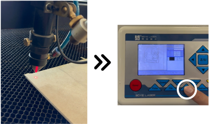
- Select the uploaded file: Go to the “File” menu and locate the file with the corresponding name. Then, press “Enter.”
- Execute a “Frame”: Before starting the actual cut, run a “Frame” to ensure that the printing area aligns correctly with the material. If not, adjust the material’s position as needed.
- Confirm everything is in order: Verify that the cutting process will proceed smoothly. If you are confident that everything is ready, proceed to the next step.
- Press the “Start” button: Once you are sure, press the “Start” button to initiate the cut.
Cut process
Cut process
Conclusions and comments
The first cutting and engraving test encountered an issue: the engraving was not being performed, and the machine exhibited strange movements. After analysis, it was concluded that the amount of information sent to the machine was excessive. As a solution, we opted to separate the cutting and engraving operations. This approach allowed the process to be successfully completed, as shown in the following Fig. 9. Furthermore, based on the conducted characterization, the appropriate parameters for configuring the laser cutting machine with 3mm MDF material are as follows:
Fig. 9. Cut results
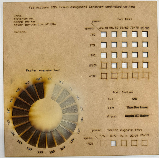
Additionally, as observed in Fig. 9, there was an error in the programming of the "Vector Engrave" power 14/15 parameter, as it should not have performed a cut. This parameter has already been corrected in the attached files in the following section.